4. Concept Detailing

Concept Detailing
2016
In PUPs #7, I really start sizing my system to get the performance I want. I select all my actuators, bearings, and mounting to put it together. I use spreadsheets to ensure feasibility and calculate the performance of my machine. In the end, I have something under $100 with about 1mm accuracy. Click on the images for links to the .pdfs and spreadsheets.
My first step was to review my requirements. My workspace, accuracy, size, power, writing, and safety requirements were all in line, but I wanted to make sure I could hit my $100 cost requirement. After doing a rough first order cost estimate, I realized that I was over budget. One of my major costs was bearings, so I decided to get rid of my Z axis to save money and time. I'd rather have an amazing 2-axis machine than a costly and hastily assembled 3-axis machine.
Now that I had solidified my decision as a 2-axis machine, I began to create an accurate error buget. I defined all my coordinate systems and talked back and forth with Alex Slocum to ensure I was using the spreadsheet correctly. In the end, it turned out that the my errors were way greater what I thought they would be. One of my biggest problems was the straightness of my rails which created systematic errors. Also, my initial machine sizing assumed my rails were mounted rigidly to my structure. Because my carraige ran on twin rails instead, I had extra load-induced error from the bending of the two simply supported shafts.
After playing around with my machine components, I was able to get my error to within 250 microns with random and load-induced error, plus another 700 microns with systematic (straightness) error for a total accuracy of 1 mm. Then I selected my sleeve bearings for my linear guides and did the calculations to assure they could handle misalginment, transmit the loads, and last a long time.
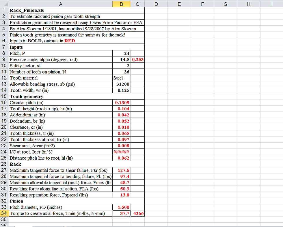
Next I had to select my linear actuator. I calculated the force and speed requirements and had to choose between leadscrew, belt, or rack & pinion. I eliminated rack & pinion because I was unsure of their accuracy and didnt want to deal with difficult mounting of the rack or the moment arm created by the pinion. It was a tough decision between belt & leadscrew since both worked. In the end I went with the leadscrew because it was cheaper and easier to mount, at the risk that it may not be able to go fast enough for my speed requirement. However, I am confident I will still be able to hit it.
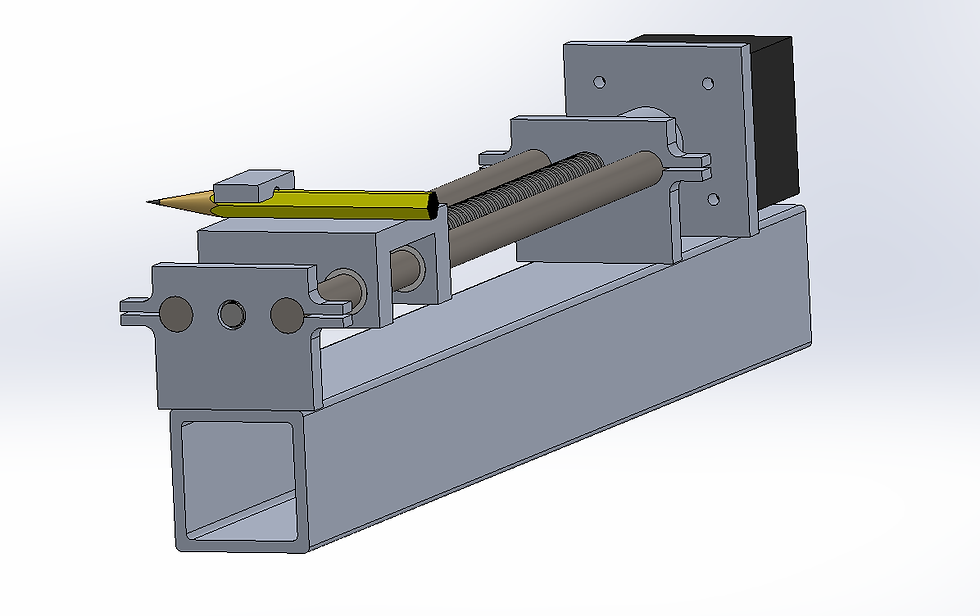
Finally, I designed my bearing support structures and carraiges. Using Saint Venant's principles, I was able to use clamps to design adjustable preloads and mount the rails. I also designed my pencil holding mechanism.
After a final requirements check, my design looks good to go!
I made a solid model of my X axis and pencil holder mechanism. This week I am going to order materials and build this. The MCM will verify my pencil holding mechanism works, and will let me know if there are any problems with my linear axis design.
-Max