3D Kinematic Coupling

I laser cut the grooves and holes into acrylic.
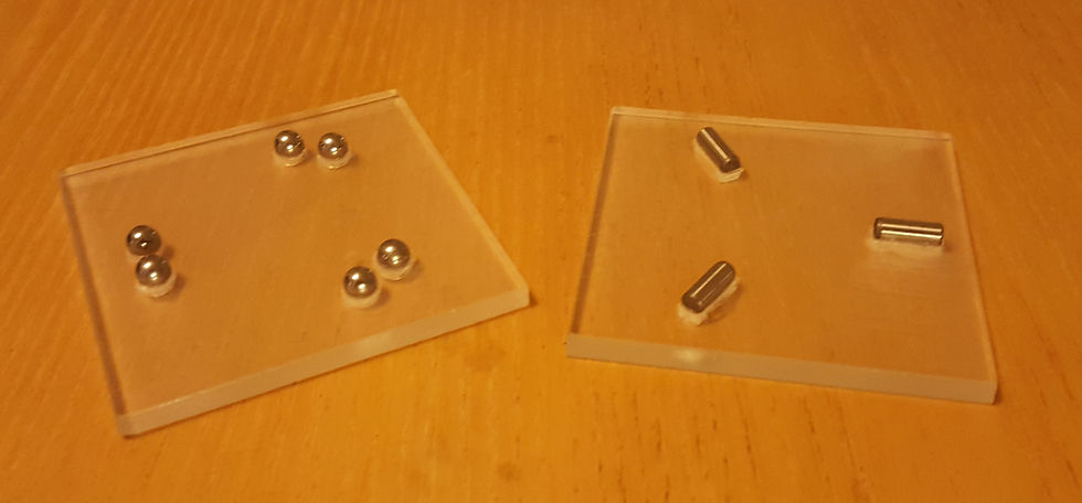
I glued the balls and dowels to the holes and grooves in the acrylic.
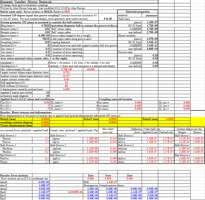
The spreadsheet I used to design my tray.
I laser cut the grooves and holes into acrylic.
Kinematic Coupling
2016
Steinbot is going to have some removable fixtures such as the paper tray and the writing utensil. A kinematic coupling allows me to place the objects to sub-micron precision. It exactly constrains the fixture and resists external forces. Here I design a kinematic coupling and compare its performance to a deterministic spreadsheet. Then I apply the principles I learned to design a kinematic coupling for SteinBot.
To make the coupling, I laser cut grooves and holes into acrylic. Usually, kinematic couplings have a 45 degrees V-groove in which a ball sits. I applied the principle of reciprocity to create a kinematic coupling with ball and dowels that were glued into the grooves and achieved point contact. Manufacturing went smoothly and I loved my coupling.
Next I tried to measure the stiffness, accuracy, and repeatability of my device. I soon realized I was not well-equipped to measure micron displacements. I had a good feel of how I would measure some of the parameters, but my calipers were not that useful. I resorted to using the thickness of the paper to make put some boundaries on the possible values.
I then used a deterministic kinematic coupling spreadsheet made by Alex Slocum and adopted it to my geometry. I found that my measurements agreed with the results. I also tried to see how some factors in the design would affect errors and stresses. I then used what I learned to create a simple design for John SteinBot's paper tray.
For my tray, the x and y errors dont matter because it doesn't matter if SteinBot begins writing 0.0002m too much into the margin. The z-directions does matter however, because an error could create additional stress on the writing utensil and break it. I realized I must use a metal like aluminum to reduce deflection in the material. Having the balls and groove make a shallow contact angle allows for less z-error. Finally, I will place my contact points as far out on the tray as I can to resist moments (learned that in my planar constraint).
Mostly, I learned that I need to improve in measuring displacements errors to calculate accuracy, reliability, and stiffness. I need to learn the method and get the tool to do it. My peers suggested using a laser at a far distance to measure angular displacement which was neat. In the end, requirements are no good if you can't verify them!